Vision
Using 2D projection to build 3D geometry
World coordinate system
One point $\mathbf{P}$ the world coordinate is represented by its coordinates:
$\mathbf{P} = (X_w,Y_w,Z_w)$
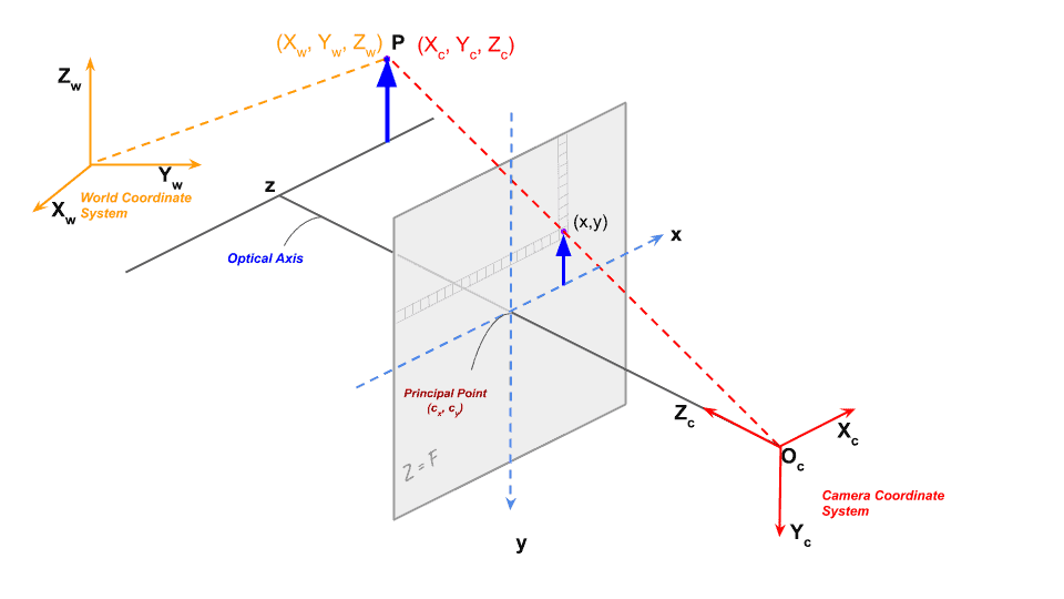
[from https://learnopencv.com]
Camera coordinate system
The same point $\mathbf{P}$ can also be represented in a coordinate system linked to the camera
$\mathbf{P} = (X_c,Y_c,Z_c)$
The camera is considered as a solid, with a center of projection $O_c$, its relative position is defined by a translation $\mathbf{T}$ and a rotation $\mathbf{R}$
$\mathbf{T} = (t_X,t_Y,t_Z)$
The rotation $\mathbf{R}$ in the 3D space is defined by three values (e.g.Euler's angles) but is represented in the form of a 3x3 matrix. All 3D rotation can be represented as a 3x3 matrix but not all 3x3 matrix are rotations.
example:
$\mathbf{R} = R_z(\alpha) \, R_y(\beta) \, R_x(\gamma)$
$R_z(\alpha) = \begin{bmatrix} \cos \alpha & -\sin \alpha & 0 \\ \sin \alpha & \cos \alpha & 0 \\ 0 & 0 & 1 \\ \end{bmatrix}$
$R_y(\beta)=\begin{bmatrix} \cos \beta & 0 & \sin \beta \\ 0 & 1 & 0 \\ -\sin \beta & 0 & \cos \beta \\ \end{bmatrix}$
$R_x(\gamma)=\begin{bmatrix} 1 & 0 & 0 \\ 0 & \cos \gamma & -\sin \gamma \\ 0 & \sin \gamma & \cos \gamma \\ \end{bmatrix}$
$\mathbf{R} = \begin{bmatrix} \cos\alpha\cos\beta & \cos\alpha\sin\beta\sin\gamma - \sin\alpha\cos\gamma & \cos\alpha\sin\beta\cos\gamma + \sin\alpha\sin\gamma \\ \sin\alpha\cos\beta & \sin\alpha\sin\beta\sin\gamma + \cos\alpha\cos\gamma & \sin\alpha\sin\beta\cos\gamma - \cos\alpha\sin\gamma \\ -\sin\beta & \cos\beta\sin\gamma & \cos\beta\cos\gamma \\ \end{bmatrix}$
One can express indeferently the coordinate of a point in both world or camera coordinate system using:
$\begin{bmatrix} X_c \\ Y_c \\ Z_c \\ \end{bmatrix} = \mathbf{R} \begin{bmatrix} X_w \\ Y_w \\ Z_w \\ \end{bmatrix} + \mathbf{T}$
Extrinsic parameters
The combination of translation and rotation is called the extrinsic parameters of the camera. Using the homogeneous coordinates:
$\begin{bmatrix} X_c \\ Y_c \\ Z_c \\ 1 \end{bmatrix} = \begin{bmatrix} \mathbf{R} | \mathbf{T}\end{bmatrix} \begin{bmatrix} X_w \\ Y_w \\ Z_w \\ 1 \end{bmatrix}$
and
$\begin{bmatrix} \mathbf{R} | \mathbf{T}\end{bmatrix} = \begin{bmatrix}\mathbf{R}_{3 \times 3} & \mathbf{T}_{3 \times 1} \\ 0_{1 \times 3} & 1\end{bmatrix}_{4 \times 4}$
Image coordinate system
Once projected on the sensor, the light coming from the scene is projected on a 2D surface. The camera has its optical center in $O_c$, and is looking at $\mathbf{P}=(X_c,Y_c,Z_c)$. The optical axis of the camera is arbitrarily pointing in the $Z_c$ direction.
The pinhole camera model

[from wikimedia]
The $(x,y)$ position of the pont $\mathbf{P}$ projected on the sensor is given by:
$x=f\frac{X_c}{Z_c}$
$y=f\frac{Y_c}{Z_c}$
where $f$ is the focal length of the camera optics. In the matrix form it can be written as:
$\begin{bmatrix} x' \\ y' \\ z' \end{bmatrix}=\mathbf{K}\begin{bmatrix} X_c \\ Y_c \\ Z_c \end{bmatrix}$
with $x = \frac{x'}{z'}$ and $y = \frac{y'}{z'}$
and
$\mathbf{K}=\begin{bmatrix} f & 0 & 0 \\ 0 & f & 0 \\ 0 & 0 & 1 \\ \end{bmatrix}$
The above 3x3 matrix is called intrinsic matrix of the camera, in this case for a pinhole camera.
Intrinsic parameters
Of course not all the camera are ideal pinhole camera. In general pixels might not be squared, meaning that two different focal length should be considered, $\mathbf{K}$ becomes:
$\mathbf{K}=\begin{bmatrix} fx & 0 & 0 \\ 0 & fy & 0 \\ 0 & 0 & 1 \\ \end{bmatrix}$
and of course the $(0,0)$ coordinate on the sensor might not be equal to the intersection of the $Z_c$ axis and the projection plane, if the optical center is $(c_x,c_y)$, the matrix becomes:
$\mathbf{K}=\begin{bmatrix} fx & 0 & c_x \\ 0 & fy & c_y \\ 0 & 0 & 1 \\ \end{bmatrix}$
and the camera sensor might also have a skew, between the x and y axis. The intrinsic matrix becomes:
$\mathbf{K}=\begin{bmatrix} fx & \gamma & c_x \\ 0 & fy & c_y \\ 0 & 0 & 1 \\ \end{bmatrix}$
From the world coordinate to the pixel
So wrapping all together, we have:
$\begin{bmatrix} x'\\ y'\\ z'\end{bmatrix}=K\, \begin{bmatrix} R | T\end{bmatrix}\begin{bmatrix} X_{w}\\ Y_{w}\\ Z_{w}\\ 1\end{bmatrix} =M \begin{bmatrix} X_{w}\\ Y_{w}\\ Z_{w}\\ 1\end{bmatrix}$
where $M = K\, \begin{bmatrix} R | T\end{bmatrix}$
$K=\begin{bmatrix} f_{x} & \gamma & c_{x} & 0\\ 0 & f_{y} & c_{y} & 0\\ 0 & 0 & 1 &0 \end{bmatrix}$
is the intrinsic matrix using homogeneous coordinates
and $ \begin{bmatrix} R | T\end{bmatrix}$ the extrinsic parameters
Camera calibration
Camera calibration is important to know the intrinsic parameters. Furthermore other distortions, due to imperfection of the sensor or the optics should be taken into account.


[from wikimedia]
Camera calibration can be done by acquiring known geometry from several angle, e.g. using a chessboard.
demo/calibration